Fuel & fuel supply system
--------------------------
Fuel is a substance consumed by the engine to produce energy. The common fuels for IC engines are: (i) petrol, (ii) power kerosene, (iii) high speed diesel oil (H.S.D oil) and (iv) light diesel oil (L.D.O)
Quality of fuel : The quality of fuel mainly depends upon the following properties: (i) volatility, (ii) calorific value and (iii) ignition quality of fuel. A good fuel contains a combination of qualities such as good volatility, high antiknock value, chemical purity, and freedom from gum.
Volatility : It is the vaporizing ability of a fuel at a given temperature. It indicates the operating characteristics of the fuel inside the engine. It is measured by means of distillation tests on the fuel. In IC engine, all the liquid fuel must be converted into vapour fuel before burning. Petrol which shows lower initial and final boiling points, compared to other fuels, vaporizes at a lower temperature. HSD oil is most difficult to vaporize. Its vaporizing temperature is higher than that of the petrol, hence the petrol vaporizes quicker than diesel oil in the engine cylinder. This helps in easy starting of petrol engines. The oil that vaporizes quickly can be distributed well in different cylinders of the engine, hence distribution of fuel in different cylinders is better in petrol engine than that of diesel engine.
Calorific value : The heat liberated by combustion of a fuel is known as calorific value or heat value of the fuel. It is expressed in kcal/kg of the fuel. Calorific values (kcal/kg) of different fuels are as follows:
1) Petrol – 11,100 (highest)
2) Power kerosene – 10,850
3) High speed diesel oil (HSD oil)- 10,550
4) Light diesel oil (LDO oil) – 10,300
Fuel Supply System
Ignition quality: It refers to ease of burning the oil in the combustion chamber. Octane number and cetane number are the measures of ignition quality of the fuel. Octane number is standard yardstick for measuring knock characteristics of fuels. Cetane number is the relative measure of the interval between the beginning of injection and auto-ignition of the fuel. The higher the cetane number, the shorter the delay interval and the greater its combustibility. Fuels with low cetane Numbers will result in difficult starting, noise and exhaust smoke.
Detonation: Detonation or engine knocking refers to violent noises heard in an engine during the process of combustion after the piston has passed over the TDC. It is an undesirable combustion and results in sudden rise in pressure, a loss of power and overheating of the engine. This may cause damage to pistons, valves, gasket and other parts. Detonation is caused by improper combustion chamber, high compression pressure, early ignition timing, improper fuel and inadequate cooling arrangement.
Pre-ignition: Burning of air-fuel mixture in the combustion chamber before the piston has reached the TDC is called pre-ignition. This may be due to excessive heat in the cylinder.
Fuel supply system in compression ignition engine or diesel engine :The main components of the fuel supply system in diesel engine are: (i) fuel tank, (ii) primary fuel filter, (iii) fuel transfer pump or fuel lift pump, (iv) secondary fuel filter, (v) fuel injection pump, (vi) high pressure pipes, (vii) fuel injection nozzles or fuel injectors and over flowpipe
During engine operation, the fuel is supplied by gravity from fuel tank to the primary filter where coarse impurities are removed. From the primary filter, the fuel is drawn by fuel transfer pump. This pump is also known as fuel lift pump, is activated by a cam on the engine camshaft. The fuel lift pump forces fuel under low pressure (2.5 kg/cm2) through the secondary fuel filter to the injection pump, which is generally driven by the camshaft. The purpose of fuel injection pump is to deliver a metered quantity of fuel at a predetermined time under pressure (120 to 175 kg/cm2 or more) through the high pressure tubes to the injection nozzles or injectors. The fuel that leaks out from the injection nozzles passes out through leakage pipe and returns to the fuel tank through the over flow pipe. In some tractors and industrial engines, the fuel supply is by gravity and hence no fuel lift pump is provided.
Two conditions are essential for efficient operation of the system:
-------------------------------------------------------------------
(a) The fuel should be clean, free from water, suspended dirt, sand or other foreign matter.
(b) The fuel injection pump should create proper pressure, so that diesel fuel may be perfectly atomized by injectors at proper time and quantity.
Components of fuel supply system Fuel tank
-------------------------------------------
It is a storage tank of suitable size and shape, usually made of mild steel sheet. Atmospheric pressure is maintained in the tank with the help of a pinhole on the cap. Usually a wire gauge strainer is provided under the cap to prevent foreign particles. Usually a drain plug is provided at the bottom for flow of fuel.
Fuel lift pump It transfers adequate amount of fuel from the fuel tank to the inlet gallery of the injection pump through fuel filter. The fuel pressure at the fuel lift pump in the range of 1.5 to 2.5 kg/cm2. It is mounted on the body of fuel injection pump. Fuel lift pump may be (i) plunger type, (ii) diaphragm type.
Fuel filter It is a device to remove dirt and solid particles from the fuel to ensure trouble free fuel supply. Solid particles and dust in diesel fuel are very harmful for giving a fine degree of filtration. Fuel injection equipment in diesel engines is extremely sensitive to dirt and solid particles present in fuel. It consists of a hollow cylindrical element contained in a shell, an annular space being left between the shell and the element. The filtering element consists of metal gauge in conjunction with various media such as packed fibers, woven cloth, felt, paper etc. These filters are replaced at certain intervals, specified by the manufacturer.
Usually there are two filters in diesel engine: (1) Primary filter and (2) secondary filter. The primary filter removes water and coarse particle of dirt from the fuel. The secondary filter removes fine sediments from the fuel. Usually the primary filter is placed between the tank and the fuel lift pump.
Fuel injection pump: It is a high pressure pump, which delivers metered quantity of fuel to each cylinder at appropriate time under pressure according to the firing order of the engine. It is used to create pressure varying from 120 to 175 kg/cm2. Fuel injection pumps are mostly constant stroke type and in most of the tractors there is an individual pump for each cylinder. The pumps used in tractor are of two types: (i) multi element pump and (ii Distributor (Rotor) type pump.
Multi element injection pump: The plunger reciprocates in close fitting barrel with the help of tappet and spring. The upper part of the plunger has got helix, which makes it possible to vary the delivery of the fuel. An annular groove in the central part of the plunger facilitates the distribution of fuel over the barrel. As the plunger moves down, the fuel enters the barrel from inlet side. As plunger moves up, it closes the inlet part of the barrel and pressurizes the fuel in the barrel. This causes delivery valve to lift off its seat and allows the fuel to enter into the injection line, leading to the fuel injector. As soon as the edge of the helix uncovers the split part of the barrel, the fuel pressure quickly drops. The cam shaft of the fuel injection pump is driven directly from the engine timing gear
Distributor (rotor) type pump: In this type of pump, one plunger and one barrel assembly deliver fuel not to one cylinder but to several cylinders. The plunger not only reciprocates, but rotates in a close fitting barrel. This helps in distributing fuel to a number of cylinders at a time.
Fuel injector : It is the component which delivers finely atomized fuel under high pressure to the combustion chamber of the engine. Modern tractor engines use fuel injectors which have multiple holes.
Air cleaner: It is a device, which filters and removes dust, moisture and other foreign matter from the air before if reaches the engine cylinder.
Air cleaner is usually of two types:
------------------------------------
(1) Dry type air cleaner
(2) Oil bath type air cleaner.
Dry type air cleaner: The filtering element in this case is a type of felt. The felt has got larger surface area, reduces the air speed while passing through and consequently particle or dirt in the air is deposited on or stopped by its surface.
Oil bath type air cleaner: In this type of air cleaner, the incoming air impinges upon the surface of the oil, kept in a container in the lower part of the casing. The foreign particles of the air are trapped in the oil and then the air passes through a wire element before reaching the inlet manifold of the engine. The wire element also arrests the remaining dirt particles of the air.
Governor : Governor is a mechanical device designed to control the speed of an engine within specified limit used on tractor or stationary engine for: (i) maintaining a nearly constant speed of engine under different load conditions (ii) protecting the engine and the attached equipments against high speeds, when the load is reduced or removed. Tractor engines are always fitted with governor. There is an important difference in principle between the controls of a tractor engine and that of a motor car. In case of motor car, the fuel supply is under direct control of the accelerator pedal, but in tractor engine, the fuel supply is controlled by the governor. The operator changes the engine speed by moving the governor control lever.
A governor is essential on a tractor engine for the reason that load on the tractor engine is subjected to rapid variation in the field and the operator can not control the rapid change of the engine speed without any automatic device. For example, if the load on the tractor is reduced, the engine would tend to race suddenly. If the load is increased, the engine would tend to slow down abruptly. Under these circumstances, it becomes difficult for the operator to regulate always the throttle lever to meet the temporary changes in the engine load. A governor automatically regulates the engine speed on varying load condition and thus the operator is relieved of the duty of constant regulating the throttle lever to suit different load conditions.
Principle of governor
Engine Governor is used for automatically controlling the speed of an engine regulating the intake of fuel or injection fuel, so that engine speed is maintained at the desired level under all conditions of loading.
Governing system is classified as:
-----------------------------------
(i) Hit and miss system,
(ii) Throttle system
Cooling System
Fuel is burnt inside the cylinder of an internal combustion engine to produce power. The temperature produced on the power stroke of an engine can be as high as 1600ºC and this is greater than melting point of engine parts. The cylinder and cylinder head are usually made of cast iron and pistons in most cases are made of aluminium alloy. It is estimated that about 40 % of total heat produced is passed to the atmosphere via the exhaust, 30 % is removed by cooling system and only about 30% is used to produce useful power.
Bad effect of high temperature in the engine (i) Cylinder and piston may expand to such an extent that the piston would seize in the cylinder and stop the engine. (ii) Lubricating quality of the oil inside the cylinder would be destroyed due to high temperature and there may not be sucking of air in the cylinder. (iii) Pre-ignition of fuel mixture would take place and would cause engine knocking as well as loss of power. For satisfactory performance of the engine, neither overheating nor over-cooling is desirable. Experiments have shown that best operating temperature of I.C engine lies between 140ºF to 200 ºF, depending upon types of engines and load conditions
Purpose of cooling
------------------
(i) To maintain optimum temperature of engine for efficient operation under all conditions. (ii) To dissipate surplus heat for protection of engine components like cylinder, cylinder head, piston, piston rings and valves. (iii) To maintain the lubricating property of the oil inside the engine cylinder for normal functioning of the engine. There are two different methods of cooling: (i) air cooling and (ii) water cooling.
Air cooling: Air cooled engines are those engines, in which heat is conducted from the working components of the engine to the atmosphere directly. In such engines, cylinders are generally not grouped in a block.
Principle of air cooling: The cylinder of an air cooled engine has fins to increase the area of contact of air for speedy cooling. The cylinder is normally enclosed in a sheet metal casing called Cowling. The flywheel has blades projecting from its face, so that it acts like a fan drawing air through a hole in the cowling and directing it around the finned cylinder. For maintenance of air cooling system, passage of air is kept clean by removing grasses etc. This is done by removing the cowling and cleaning out the dirt etc. by a stiff brush or compressed air. When separate fan is provided, the belt tension is to be checked and adjusted if necessary.
Advantages of air cooling: It is simpler in design and construction. Water jackets, radiators, water pump, thermostat, pipes, hoses etc. are not needed. It is more compact. It is comparatively lighter in weight.
Disadvantages of air cooling: There is uneven cooling of the engine parts. Engine temperature is generally high during working period. Water cooling Engines,
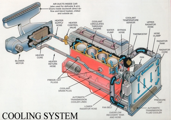
using water as cooling medium is called “water cooled engines”. The liquid is circulated round the cylinders to absorb heat from the cylinder walls. In general, water is used as cooling liquid. The heated water is conducted through a radiator which helps in cooling the water. There are three common methods of water cooling: (i) Open jacket or hopper method, (ii) Thermo siphon method, and (iii) Forced circulation method. Forced circulation method :In this method, a water pump is used to force water from the radiator to the water jacket of the engine. After circulating the entire run of water jacket, hot water goes to the radiator, where it passes through tubes surrounded by air. A fan is driven with the help of a V-belt to suck air through tubes of the radiator unit, cooling radiator water. To maintain the correct engine temperature, a thermostat valve is placed at the outer end of cylinder head. Cooling liquid is by-passed through the water jacket of the engine until engine attains the desired temperature. Then thermostat valve opens and the by-pass is closed, allowing the water to go to the radiator. The system consists of water pump, radiator, fan, fan-belt, water jacket, thermostat valve, temperature gauge and hose pipe
Cooling System
Working of forced circulation cooling system
---------------------------------------------
Water pump: It is a centrifugal type pump. It has a casing and an impeller, mounted on a shaft. The casing is usually made of cast iron. Pump shaft is made of some non-corrosive material. At the end of the shaft, a small pulley is fitted which is driven by a V-belt. Water pump is mounted at the front end of the cylinder block between the block and the radiator. When the impeller rotates, the water between the impeller blades is thrown outward by centrifugal force and thus water goes to the cylinder under pressure. The pump outlet is connected by a hose pipe to the bottom of the radiator. The impeller shaft is supported on one or more bearings. There is a seal which prevents leakage of water.
Radiator: Radiator is a device for cooling the circulating water in the engine. It holds a large volume of water in close contact with a large volume of air so that heat is transferred from the water to the air easily. Hot water flows into thee radiator at the top and cold water flows out from the bottom. Tubes or passages carry the water from the top of the radiator to the bottom, passing it over a large metal surface. Air flows between the tubes or through the cells at right angles to the downward flowing water. This helps in transferring the heat from the water to the atmosphere. On the basis of fabrication, the radiator is of two types: tubular type and cellular type. Tubular type radiator: It has round or flat water tubes, leading from the top to the bottom of the radiator. They may be soldered, brazed or welded in place or fastened by means of a stuffing box at each end. Fins or folded strips of light sheet metal, placed between the tubes, increase the radiating surface and improve the heat transfer. Cellular type radiator: It has a core made of short air tubes which are laid horizontally and soldered together at the ends with space between them to allow water to flow. It is also called Honey comb type radiator.
Thermostat valve: It is a control valve, used in the cooling system to control the flow of water when activated by a temperature signal.
Ignition system: Fuel mixture of I. C engine must be ignited in the engine cylinder at proper time for useful work. Arrangement of different components for providing such ignition at proper time in the engine cylinder is called ignition system. There are four different systems of igniting fuel: (i) ignition by electric spark i.e., spark ignition, (ii) ignition by heat of compression i.e. compression ignition, (iii) ignition by hot tube or hot bulb and (iv) ignition by open flame. Only the first two are important methods for modern engines.
Spark ignition: The purpose of spark ignition is to deliver a perfectly timed surge of electricity across an open spark plug gap in each cylinder at the exact moment, so that the charge may start burning with maximum efficiency. There are two methods in spark ignition: (a) Battery ignition and (b) Magneto ignition.
Battery ignition:
-----------------
Principle: Battery ignition system includes two circuits: low voltage (primary circuit) and high voltage (secondary circuit). The low-voltage circuit consists of : (i) battery (ii) ignition switch (iii) a series register (IV) primary winding and (v) contact breaker. All are connected in series. The high voltage circuit consists of: (i) secondary winding (ii) distributor rotor (iii) high voltage wiring and (iv) spark plugs. They are also connected in series. Battery ignition system on a modern tractor includes a storage battery, ignition switch, high tension coil, distributor, contact breaker mechanism, condenser, spark plugs, generator and cut-out.
Working: Electric current is supplied by the battery to the ignition circuit. When the distributor breaker points are closed, low voltage current flows through the primary winding of the ignition coil to the distributor terminal and through the breaker points to the ground. During this time, a strong magnetic field built up in the coil. When the piston is at the end of compression stroke, the distributor points are opened, the magnetic field in the coil starts collapsing. Thus, a current is induced in the primary winding of the coil, which tends to prevent break down of the magnetic field.
A very high voltage is produced in the secondary winding due to sudden collapse of the magnetic field. This sudden collapse of the magnetic field in the coil, produces a very high voltage across the secondary winding terminals to a value of 20 to 24 thousand volts. The high-voltage surge is delivered to the centre terminal of the distributor cap, where it is picked up by the rotor and directed to the proper spark plug. The high voltage is capable of jumping the spark across the gap of the spark plug and ignites the compressed air-fuel mixture (Fig.10). This system of a number of components such as: (i) Spark plug (ii) Distributor (iii)Ignition coil(iv)Condenser (v) Ignition switch (vi) Dynamo and (vii) Storage battery
Spark plug : ignites the air –fuel mixture in combustion chamber. It is a device for the high voltage current to jump and ignite the charge. Each spark plug consists of a threaded outer shell with an outside electrode, insulator and a copper gasket. The width of the gap between the points of the two electrodes of a spark plug should conform to the manufacturers. If the clearance is too wide, it does not give satisfactory operation. Usually the spark plug gap settings are kept between 0.5 and 0.85 mm. The higher the compression pressure, the more difficult it is for the current to jump the gap. In this case, the gap setting should be closer. In adjusting the spark plug gap, it is always the outer electrode that is bent. The central electrode is never bent, otherwise the porcelain insulator may break. Sometimes, one or more cylinders of a tractor engine do not fire, or fire irregularly. This is generally due to dirty, cracked or ground plugs. A rich mixture causes carbon deposits on the plugs. Under all circumstances, the plugs should be taken out and cleaned properly. The heat range of the spark plug is determined by the distance the heat must travel from the lower most tip of the central electrode to the engine block (via) the spark plug gasket. The farther the heat travels, the hotter the plug will run. Based on this, the spark plugs classified into two types: (a) cold plug and (b) hot plug. Cold plug has a short insulator, extending into the cylinder. It conducts the heat away from the point rapidly, allowing it to be cooled by the cylinder jacket. The short path dissipates heat quickly, so it is named as cold plug. Cold plugs are used on petrol engines. Hot plug has comparatively longer insulator, so the heat has to pass through a longer path to reach the cooling water and hence the heat is not dissipated quickly. Hot plugs are used for power in engines.
Distributor : This is a rotary switch driven by the engine through gears at half the engine speed. This device used for interrupting the low voltage primary current and distributing the resulting high voltage current to the engine cylinder in proper sequence and in proper time. The main functions of distributor are: (i) it closes and opens the primary circuit. (ii) it distributes the resulting high voltage current to the engine cylinder in proper sequence and in proper time. Distributor cap is made of Bakelite or similar non-conducting material. High-tension cables connect the terminals in the distributor cap to the spark plug.
Ignition coil : It serves the purpose of a small transformer, which sets up low voltage (may be 6 volts) to very high voltage (may be 20,000 volts). It is necessary to jump the gap of the spark plug. The ignition coil is sealed to prevent entry of moisture which would cause short
Condenser : A condenser consists of a pair of flat metal plates, separated by air. The most common type of condenser is of metal foil strips, separated by wax impregnated paper. The condenser in the distributor is connected across the contact breaker points. It is used to produce a quick collapse of the magnetic field in the coil to obtain extremely high voltage. In doing so, the condenser prevents sparking across the contact breaker points, thus preventing the points from burning.
Ignition switch : A switch is provided in the primary circuit for starting and stopping the engine is called ignition switch. It may be push pull type or key type.
Dynamo : The purpose of the dynamo is to keep the battery charged and to supply current for ignition, light and other electrical accessories. The dynamo supplies direct current to the battery and keeps it fully charged.
Storage battery : Storage battery is a device for converting chemical energy into electrical energy. There are several types of battery, but lead-acid battery is most common for IC engines, used for tractors and automobiles. A battery consists of plates, separators, electrolyte, container and terminal wire.
Plates are of two types:
(i) positive
(ii) negative.
All positive and negative plates are rectangular in shape. All positive plates are connected together to form a positive group and negative plates are connected together to form a negative group. Positive plates are made of lead and antimony and negative plates are made of spongy lead. Separators are used to act as insulators between the plates to prevent them from touching each other to avoid short-circuiting. Usually separators are made of wood, rubber and cellulose fibre. Electrolyte is the chemical solution used in battery for chemical reaction. It consists of 35% sulphuric acid and 65% distilled water by weight with a specific gravity of 1.280 in fully charged condition. The specific gravity is measured by hydrometer. The electrolyte level should be 12 to 14 mm above the top edge of the plates. Specific gravity of the electrolyte should be checked at suitable interval. If the specific gravity is below 1.225, it should be charged. Container is usually made of hard rubber. The tops are covered with rubber material and sealed with a water proof compound. Terminal wires are two in number, one connects the positive terminal and other connects the negative terminal with the electric circuit.
Power transmission system
-------------------------
Transmission is a speed reducing mechanism, equipped with several gears . It may be called a sequence of gears and shafts, through which the engine power is transmitted to the tractor wheels. The system consists of various devices that cause forward and backward movement of tractor to suit different field condition. The complete path of power from the engine to the wheels is called power train
Power Transmission System
Function of power transmission system
-------------------------------------
(i) To transmit power from the engine to the rear wheels of the tractor. (ii) to make reduced speed available, to rear wheels of the tractor. (iii) to alter the ratio of wheel speed and engine speed in order to suit the field conditions. (iv) to transmit power through right angle drive, because the crankshaft and rear axle are normally at right angles to each other. The power transmission system consists of: (a) clutch, (b) transmission gears (c) differential, (d) final drive, (e) rear axle, (f) rear wheels. Combination of all these components is responsible for transmission of power.
Clutch: Clutch is a device, used to connect and disconnect the tractor engine from the transmission gears and drive wheels. Clutch transmits power by means of friction between driving members and driven members. Necessity of clutch in a tractor Clutch in a tractor is essential for the following reasons: (i) Engine needs cranking by any suitable device. For easy cranking, the engine is disconnected from the rest of the transmission unit by a suitable clutch. After starting the engine, the clutch is engaged to transmit power from the engine to the gear box. (ii) In order to change the gears, the gear box must be kept free from the engine power, otherwise the gear teeth will be damaged and engagement of gear will not be perfect. This work is done by a clutch. (iii) When the belt pulley of the tractor works in the field it needs to be stopped without stopping the engine. This is done by a clutch.
Essential features of a good clutch
(i) It should have good ability of taking load without dragging and chattering.
(ii) It should have higher capacity to transmit maximum power without slipping.
(iii) Friction surface should be highly resistant to heat effect.
(iv) The control by hand lever or pedal lever should be easy.
Types of clutch: Clutches are mainly of three types: (1) Friction clutch (2) Dog clutch (3) Fluid coupling. Friction clutch (Fig.12) is most popular in four wheel tractors. Fluid clutch is also used in some tractors these days. Dog clutch is mostly used in power tillers. Friction clutch may be subdivided into three classes: (a) Single plate clutch or single disc clutch (b) Multiple plate clutch or multiple disc clutch (c) Cone clutch.
Gears : Speed varies according to the field requirements and so a number of gear ratios are provided to suit the varying conditions. Gears are usually made of alloy steels. As the tractor has to transmit heavy torque all the time, best quality lubricants free from sediments, grit, alkali and moisture, is used for lubrication purpose. SAE 90 oil is generally recommended for gear box.
Differential : Differential unit is a special arrangement of gears to permit one of the rear wheels of the tractor to rotate slower or faster than other. While turning the tractor on a curve path, the inner wheel has to travel lesser distance than the outer wheel. The inner wheel requires lesser power than the outer wheel, this condition is fulfilled by differential unit, which permits one of the rear wheels of the tractor to move faster than the other at the turning point.
Differential lock : Differential lock is a device to join both half axles of the tractor so that even if one wheel is under less resistance, the tractor comes out from the mud etc as both wheels move with the same speed and apply equal traction.
Final drive: Final drive is a rear reduction unit in the power trains between the differential and drive wheels.
Lubrication System
-------------------
IC Engine is made of many moving parts. Due to continuous movement of two metallic surfaces over each other, there is wearing of moving parts, generation of heat and loss of power in the engine. Lubrication of moving parts is essential to prevent all these harmful effects.
Purpose of lubrication
-----------------------
Lubrication of the moving parts of an IC Engine performs the following functions:
(i) Reduces the wear and prevents seizure of rubbing surfaces (Reduce wear)
(ii) Reduces the power needed to overcome the frictional resistance (Reduce frictional effect).
(iii) Removes the heat from the piston and other parts (Cooling effect)
(iv) Serves as a seat between piston rings and cylinder (Sealing effect)
(v) Removes the foreign material between the engine working parts (Cleaning effect)
Reducing frictional effect
The primary purpose of the lubrication is to reduce friction and wear between two rubbing surfaces. The continuous friction produces heat which causes wearing of parts and loss of power. This can be avoided by proper lubrication, which forms an oil film between two moving surfaces.
Lubricating System
Cooling effect : The heat generated by piston, cylinder and bearings is removed by lubrication to a great extent. Lubrication creates cooling effect on the engine parts.
Sealing effect : The lubricant enters into the gap between the cylinder liner, piston and piston rings. Thus, it prevents leakage of gases from the engine cylinder.
Cleaning effect : Lubrication keeps the engine clean by removing dirt or carbon from inside of the engine along with the oil.
Types of Lubricants : Lubricants are obtained from animal fat, vegetables and minerals. Lubricants made of animal fat, does not stand much heat. It becomes waxy and gummy which is not very suitable for machines.
Vegetable lubricants are obtained from seeds, fruits and plants. Cotton seed oil, Olive oil, linseed oil and Castor oil are used as lubricant in small simple machines. Mineral lubricants are most popular for engines and machines. It is obtained from crude petroleum found in nature. Petroleum lubricants are less expensive and suitable for IC Engines.
Engine lubricating system
-------------------------
The lubricating system of an engine is an arrangement of mechanism and devices which maintains supply of lubricating oil to the rubbing surface of an engine at correct pressure and temperature. The parts which require lubrication are:
(i) cylinder walls and piston, (ii) piston pin (iii) crankshaft and connecting rod bearings (iv) cam shaft bearings (v) valves and valve operating mechanism (vi) cooling fan (vii) water pump and (viii) ignition mechanism. There are three common systems of lubrication used on stationery engines, tractor engines and automobiles: (i) splash system, (ii) forced feed system, and (iii) combination of splash and forced feed syste
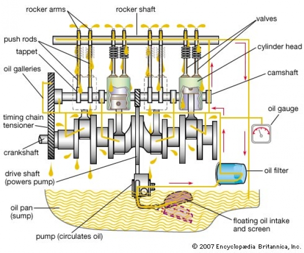
Forced feed system
-------------------
In this system, the oil is pumped directly to all the moving parts (i.e., crankshaft, connecting rod, piston pin, timing gears and cam shaft) of the engine through suitable paths of oil (Fig.14). Lubricating oil pump is a positive displacement pump, usually gear or vane type, which is driven by the camshaft, forces oil from the crankcase to all crankshaft, and connecting rod bearings, cam shaft bearings and timing gears. Usually the oil first enters the main gallery, which may be a pipe or a channel in the crankcase casting. From this pipe, it passes to each of the main bearings through holes. From main bearings, it passes to big end bearings of connecting rod through drilled holes in the crankshaft. From there, it passes to lubricate the walls, pistons and rings. There is separate oil gallery to lubricate timing gears. The oil also passes to valve stem and rocker arm shaft under pressure through an oil gallery. The excess oil comes back from the cylinder head to the crankcase. The pump discharges oil into oil pipes, oil galleries or ducts, leading to different parts of the engine. The system is commonly used on high speed multi-cylinder engine in tractors, trucks and automobiles
Gearbox Operation With Clutch
� 2013 Agricultural Educatorium, Navsari Agricultural University, Navsari. All Rights Reserved
Managed by: IT Cell, Navsari Agricultural University, Navsari.